Showing posts with label CAD. Show all posts

Friday, 16 January 2015

Radical SR8 RSX Spyder

A few weeks ago we visited the Autosport Show at the NEC to see the unveiling of some of our latest work.

Over the past five months we have spent every available hour working on the exterior design and CAD modelling of the bodywork for the new Radical SR8 RSX Spyder race car. Unfortunately, this has put a temporary halt on finishing other projects, but an opportunity like this could not be turned down.


The final CAD render above which was previewed at a Radical event at the Circuit de Barcelona-Catalunya during Autumn and below is the Spyder having just been unveiled at the Autosport Show.


It may be a car, and we are all bike fans here, but it certainly packs performance (there is a little video clip here of it's first test https://www.youtube.com/watch?v=7VwzfmReUHw ) and it sounds immense.

Saturday, 3 May 2014

SV650 - Air Duct Design Part 1


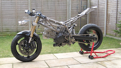
The air ducts - something thats been put low down on our priority list but has always been there. The standard airbox has an inlet that sits just beneath the underside of the fuel tank. On the basis that an engines performance increases if it can breathe more efficiently, then this seems a rather daft place to draw air in. 

So we are designing a larger airbox (using the underside of the tank as the top of the airbox) with the air ducts either side of the headstock to help draw the air in from the high pressure point on the front of the bike.

Here's how we are doing it (this will be in several parts as a work in progress and may not be the best way to do it, but is the way we are doing it!) . . .

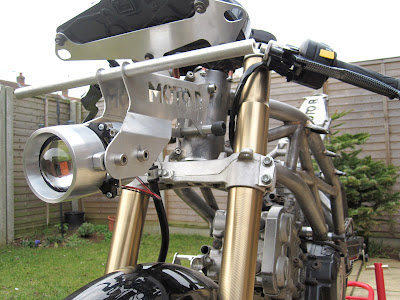
Above, we have modelled one air duct using MDF and styling clay (quick, easy and the way an Industrial Designer knows how to do it) which fits onto the bike (only one side as the other side will be a mirror image).


From the clay, we have scanned the part using a FARO Arm and processed it in CAD to give us a 3D representation of the air duct in Solidworks. If we were getting really technical at this stage, we could reverse engineer it into a manufacturable part and do all sorts of flow analysis to optimise the shape - but we didn't. 


This 3D model was then sliced in multiple 12mm parts (like a loaf of bread) to give us a number of profiles which could be cut out from MDF and laminated together to create a mold. In fact, there are four molds, one for the top and one for the bottom, then duplicates for a mirrored part to sit on the other side of the bike. (This stage could certainly be sped up by 3D printing or machining the parts from foam, but we always seem to take the hard, less expensive route).


Laminate MDF profiles then gave us these molds, which required a fair bit of sanding and filling, but these will only be used for the first prototype parts, so can still be a little rough. The important thing with these is that they are symmetrical to one another and that both the tops and bottoms fit together.


A close up of the contours. There are a lot of hard points for the air ducts to clear, such as frame tube, fork legs, fairings, light brackets and even stubborn wiring, so they have ended up with quite organic shapes. Once we get to a finish as seen above, we coat them in epoxy resin to give them a hard surface, then a quick sand down to smooth off any high points and its time to lay them up with some fibreglass.

We'll let them cure now, see what happens next in part 2 . . .


Saturday, 12 April 2014

SV650 - Swingarm Design


The bike has been sat on an ABBA stand at work for the past few weeks whilst we have had the swingarm out for measuring. This only means one thing - the trellis swingarm is finally being designed!

Due to continual demand (everyone seems to love the swingarm on the original CAD drawings) we have finally got to the point of beginning the design work on this element and below are some early ideas of how the design is developing.


We feel it is important to ensure the swingarm is designed to allow flexibilty and different combinations of rear wheel setups to be used. As we have designed the frame to be capable of taking either the early or later generation SV650 swingarm, it is important that we do the same for the swingarm, to allow riders the option of purchasing the swingarm to fit onto their standard bikes. With this in mind, both generations have been roughly modelled in CAD, in order to optimise the design of our swingarm we are planning to go with a machined aluminium dropout design in order to offer customised wheel options easily.

These are all early design ideas and we will be refining them over the coming months ready to make a prototype, so any suggestions are more the welcome.


Sunday, 1 September 2013

SV650 - Fuel Tank Refinements


Having built a tank and fitted / removed it from the bike many times, some issues were discovered which needed to be resolved.

Due to the way the tank fits around the OEM airbox and the way that it extends down one side of the rear cylinder, it was always awkward to get it into the correct location, without a bit of wriggling and partially removing the airbox. It was also impossible to run the overfolw catch tank that is attached to the airbox (not something I need, especially if racing, but would be nice to accomodate it).


So, working between the bike, the existing tank, a few cardboard templates and the original CAD model, a number of tweaks were made to the model to redesign the internal shape and lower side extension. The rubber mounting system has also been slightly modified.


It's maybe hard to see many changes from the earlier photos of the Aluminium tank, but it should hopefully make fitting and removal much easier along with manufacture, as the break down of parts to be bent has been refined.


The next stage for this is to send the drawings off for lasercut, then find someone happy to TIG weld one.

Saturday, 18 May 2013

SV650 - Front Subframe Part 1


The front subframe - designed to support the headlight and sidelights whilst holding the instrument panel in position, carrying the headlight ballast pack, mounting the lock-stops & mirrors along with supporting the front fairing. That's a lot of functions for such a small lightweight piece, so lets hope we have got the design right.


The subframe has been extensively re-worked in CAD, due to a number of modifications from the very original piece we mocked up. It's mounted lower on the headtube, to clear the ignition barrel and support the lock-stops better, shorter in length and made from 3mm, rather than 2mm sheet aluminium. It also has provision for the sidelight mounting brackets and a simplified design for the uprights to support the top of the front faring. We also decided to go with a two part main structure which will be welded along the centre, just to make it easier to bend during manufacture.


 Lasercut parts returned, so time to bend up each half of the main structure.


Both sides have an interlocking face so they can't possibly be misaligned. This joint will then be TIG welded.


A comparison against the original (modified) subframe.


On the front of the bike with the cross brace fitted to locate the lower mount on the front fairing. We also have the headlight unit fitted. These two elements are key to the structure becoming rigid.


The riders view, with the instrument panel in place. The instrument panel sits on its own mount that is riveted in place and then welded to the two uprights that will come up along either side, where those holes are.


Fairing test fit around the initial parts of the subframe. A little awkard to get everything aligned and where we wanted it. Lock-stops also fitted and limited turning circle achieved!

Next time, we'll get the uprights in place and have this all welded and on the bike with photos.


Saturday, 11 May 2013

SV650 - Just An Exhaust Hanger


It's just an exhaust hanger, but there are also a few other finished bits to highlight too. The bike is progressing well now that the composite work is all done and I'm a bit more in my comfort zone. In the next few weeks, I'll get some photos up of the front subframe completion, more details on the lighting and some more photos of final trims of the bodywork.


CAD images are always exciting, so here are some screenshots of the exhaust hanger design on the rear subframe assembly.


Below is a photo of the exhaust hanger on the bike. Also of note is the finished stainless link pipe, now fully welded and given a brushed finish. The completion of these two parts meant that the Arrow titanium silencer could be fitted and the engine run. Sounds real good! If i can work out how to get a sound clip up, I may upload a teaser.


Whilst we were having the exhaust hanger lasercut, we had a few other parts done including the heel plates and some front subframe components. The front subframe had never been finalised, due to the need of having an actual front fairing to work out the correct location of the mounting points. Now we have this, the subframe was refined and finalised in CAD. Some of these parts had a large enough change to warrant being lasercut once again, but this time in thicker 3mm aluminium. More on all these developments next time.


Moto-R Design heel plates!
 

Monday, 20 February 2012

SV650 - The Dry Build Commences


Here it is! We have started to do a dry build of all the parts manufactured so far to ensure they all fit when it comes round to put a running engine into the bike. 

The frame was always going to fit, but the front and rear subframes have been designed in CAD, so we need to have them on the bike to ensure everything aligns and the bodywork fits as it should. It also gives us chance to check all the brackets on the frame, fit the battery box, get the radiator mounts in place, locate the fuel tank . . . the list goes on.


Below you can see how the front subframe fits with the instrument panel and adjustable headlight unit. Theres still a few more pieces to TIG weld on to fully support the front fairing. The lock-stops have also been integrated into the aluminum piece


The comparison below gives you an idea of how the frame has evolved from initial mock-up, through the CAD process and into a prototype frame. Main differences are larger radius' bends in the tubes, removal of a few bosses deemed unnecessary, addition of headstock gussets & side stand bracket sand obviously a higher grade material that has been fully TIG welded.


More photos as and when progress happens!

Wednesday, 15 February 2012

SV650 - Making the Fuel Tank


The creation of the fuel tank has now transferred from CAD models into aluminum. It looks fairly complex, but the intentions are to make it out of as few a pieces as possible.


The tank has been lasercut from 4 pieces, with an internal baffle which doubles as a jig to weld everything accurately. These have all been bent to correct angles on a hydraulic press. Then there is the filler neck and various fixings to go on at the end.


Below is an extension to the tank that we designed on CAD to give us a few more liters of fuel capacity. This sits down in between the rear cylinder and frame.


The next thing to do is a test fit when the bike is built up and when everything fits as it should the tank can be tacked together ready for TIG welding.

Thursday, 27 October 2011

SV650 - Rearsets


Whilst we are waiting for some lasercutting and material to arrive to make the frame, we spent some time designing some rearsets to fit to the bike when its complete.


They have a 5-way range of adjustment, feature Needle roller bearings, knurled footpegs, anodised matt black etc. More details will be put up when they have been manufactured. Its likely that we will have to have a small quantity made, so if you are interested in some then let us know via email as they are designed to fit a standard curvy SV as well.


Friday, 7 October 2011

SV650 - Frame Closeups


The frame is also now complete in Solidworks so we have grabbed a few closeup shots of some of the details. 


Chamfered edges feature on all the bosses to minimise any excess weight.


Headstock gussets and aluminum bearing inserts. This allows for easy interchanges between different fork setups which use different sized bearings with the insert clamped into place using pinch bolts.


Wednesday, 5 October 2011

SV650 - Rear Subframe


The past few weeks have started to see some aspects of the CAD model come together so I'll be uploading more pictures of the completed pieces soon

For now, we have the rear subframe, which will be manufactured out of tubing and waterjet cut pieces.


As we are always on the quest to reduce weight and complexity, the subframe has been designed with only three main tubes in triangulation, opposed to the usual four used by most manufacturers.


The fabricated piece on the rear has multiple purposes. At the front, it supports the rear of the seat pan, at the rear fixes to the rear light unit making the whole piece rigid, and the mounts on top act as a bodywork support.